Application note
When troubleshooting electrical equipment failures or nuisance trips, one of the key details you need to know is whether the circuit in question has a non-linear load connected to it. Non-linear loads come from equipment such as computers, electronic controls, variable speed drives, and energy-conserving lighting, such as LED lighting, as well as high-efficiency HVAC systems that draw current in short pulses rather than as a smooth sine wave. These pulses cause harmonic current to flow back into other parts of the power system and produce non-sinusoidal wave shapes. The result is overheating, malfunctions, and eventually failures throughout the system.
To help get to the root of the problem you need to get an accurate measurement of the rms current and compare it to the rated rms value for the component in question. The term “rms” stands for “root mean square” which calculates the effective value (or heating value) of any ac wave shape. In electrical terms, the ac rms value is equivalent to the dc heating value of a particular voltage or current waveform. Electrical components such as fuses, bus bars, conductors, and thermal elements of circuit breakers are rated in rms current because their main limitation is related to heat dissipation.
If you’re measuring a linear load—such as standard induction motors, resistance heaters, or incandescent lights—you can easily capture accurate rms measurements with an average responding measurement tool. However, if a nonlinear load is on that circuit, you need to use a true-rms measurement tool to get an accurate rms reading, or your measurements may read up to 40 % low.

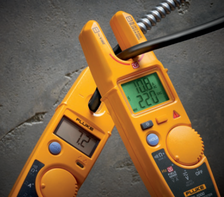
Both testers shown here are measuring the same harmonically distorted load. The T6-1000 on the right displays true-rms voltage and current measurements. The T5 average responding electrical tester on the left uses a calculated value based on a pure sine wave which produces a current value that is approximately 33 % low.
Average responding vs. true-rms
Average responding tools, such as the Fluke T5 electrical tester, calculate a value based on the assumption that what is being measured is a pure sine wave. They use a shortcut method that captures the rectified average of an ac waveform and multiplies that number by 1.11 to calculate the rms value. The result is not a true value, but rather a calculated value based on an assumption that the wave shape is a pure sine wave. If you’re measuring a load with a pure sine wave this method is very accurate.
However, if you’re measuring a circuit with a non-linear load, the reading from an average responding meter can be up to 40 % off. This can delay an accurate diagnosis of the problem and may cause you to replace components that don’t need replacement.
A true-rms-rated measurement tool is equipped with an internal circuit that calculates the heating value according to the rms formula. This method gives the correct heating value regardless of the current wave shape. As a result, you’ll be able to accurately measure the true load current to determine whether the circuit is faulty or overloaded, or whether the problem is with the load itself.
The table below gives some examples of how average responding and true-rms tools respond to different wave shapes.


Look for the true-rms label
If you only need to measure circuits with linear loads, an average responding measurement tool like the Fluke T5 will provide accurate measurements. However, if you work in environments with only non-linear loads or a mix of both types, you need to be sure that you are using a true-rms rated measurement tool.
There are all kinds of true-rms tools ranging from DMMs and current clamps to electrical testers, like the Fluke T6 Electrical Tester. To make sure the tool you choose is true-rms rated, look for the words “true-rms” on the front or back panel or review the specs. If the tool is true-rms rated, those words will appear on the tool, in the product specs or in both places. If you don’t find the true-rms spec listed, it is most probably an average-responding tool.
Measure true-rms current and voltage without test leads
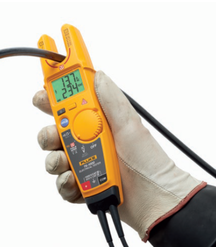
Fluke T6 Electrical Testers with integrated FieldSense technology go beyond simply detecting voltage. They measure true-rms ac voltage and current so you can quickly get accurate readings on both non-linear and linear loads. FieldSense technology eliminates the need for test leads in most instances*. Just slide the open fork over a conductor and view current, voltage or both.
Features at a glance:
- Choose from two models: the T6-1000 (1000 V ac) and the T6-600 (600 V ac)
- Simultaneously measure and display true-rms voltage and current for efficient troubleshooting
- Take advantage of FieldSense technology to measure ac voltage, current, and frequency without electrical contact to live voltage*
- Measure wires up to AWG 4/0 (120 mm2) with a 17.8 mm jaw opening
- Easily view display in low light environments with backlight
* Voltage measurement requires capacitive path to ground, provided through user in most applications. Ground connection via test lead may be required in some situations.