The digital multimeter is the mainstay of electrical troubleshooting and the tool that most of us reach for first. In Beyond the Multimeter, we look at five examples of how reaching for an oscilloscope next can make troubleshooting faster, easier, and more effective.
Part 1 describes troubleshooting a variable frequency drive (VFD).
What's Wrong with the VFD?
The smooth operation of many industrial processes requires that variable speed drives be kept in good working order. When a fault indicator comes on indicating a problem, it's important to diagnose the problem and get it fixed fast.
In this example, a variable speed drive on a critical system has a fault indication. According to the variable frequency drive, the error code is "F4." You check the code and see that it means that the drive has detected an "under voltage" condition. The drive has shut down.
Is the failure is in the drive, the motor, or a distorted supply voltage?
Troubleshooting with a Multimeter
Check the input line voltage


- A typical multimeter will display either average or rms voltage values (Figure 1)
- Depending on the type of distortion, the value shown on the multimeter may not reveal if a problem exists.
With a digital multimeter, you can check the line input voltage, but depending on the type of distortion, a voltage reading alone may not reveal whether a problem exists. Noise, distortion, or transient failures may simply not be detectable with a multimeter.
Check the VFD dc bus voltage
- Is the dc bus voltage directly proportional to the peak of the input line voltage?
- Check for any distortion or error in peak amplitude of the line voltage which can cause an over- or under voltage error (The drive dc bus voltage in Figure 2 shows around 20% under the nominal value of 160 V.)
In this example, when you check the drive's DC bus voltage, you find that it's about 20% under the nominal value. That's a problem. But do you replace the drive controller, the motor, or both? You need more information.
Troubleshooting with an Oscilloscope


Check the input line voltage
- Connect a digital oscilloscope to phase and the ground lead to neutral
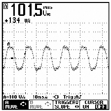
- In this example, the waveform reveals sine wave peaks that are rounder than they should be, almost becoming a "flat top" (Figure 3).
- Distorted waveforms such as those in Figure 3 don't have the peak-voltage-to-rms-voltage ratio of 1.4 of well-formed sine wave.
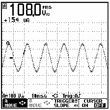
- Figure 4 shows a circuit with an ideal line voltage wave shape (a sine wave with a peak-to-rms ratio of 1.4).
An oscilloscope can give you a clearer picture of things. At the power input of the drive you connect the scope to phases L1, L2, or L3, and the ground lead to neutral. In this example, a glance at the waveform reveals almost flat-topped sine waves (Figure 3). Compare that to the ideal waveshape shown in Figure 4 and you can see the difference clearly.
Flat-top waveforms are often caused by non-linear loads attached to the same feeder circuit. With an oscilloscope, you can see that the problem doesn't lie with the VFD or the motor. The oscilloscope graphically shows not just amplitude, but also any distortion, disturbance, or noise that may be affecting the waveform, giving you the information you need to troubleshoot, diagnose, and solve problems.
The Bottom Line
The waveform distortion in this example was caused by a non-linear load attached to the same feeder circuit as the VFD, and not the VFD or motor.
A digital multimeter can display exact rms or peak amplitude values. An oscilloscope can graphically show amplitude (rms or peak) as well as any distortion, disturbance, and noise that may be present on the waveform.
A picture really is worth a thousand words!
Portable oscilloscopes are used in many field troubleshooting applications from electrical and electro-mechanical to electronic and industrial control systems.
- Beyond the Multimeter, Part 2: Using a Multimeter and an Oscilloscope to Troubleshoot Transient Voltages in Variable Frequency Drive Output
- Beyond the Multimeter, Part 3: Troubleshooting a Rotary Encoder with a Multimeter and an Oscilloscope
- Beyond the Multimeter, Part 4: Troubleshooting a Proximity Switch with a Multimeter and an Oscilloscope
- Beyond the Multimeter, Part 5: Troubleshooting a DC Power Supply with a Multimeter and an Oscilloscope