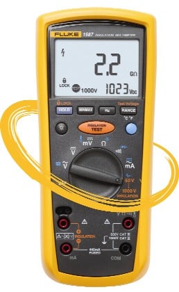
- Measuring tools: Fluke 1587 Insulation Multimeter
- Operator: Singapore electrical utility
- Tests conducted: Insulation resistance cable test, continuity, voltage
As electricity is transmitted and distributed from generation plants to the end users, it passes through numerous sections of low voltage (below 1000 V) and high voltage (defined in Singapore as more than 1000 V) cables. In addition to these transmission cables, pilot cables (which consist of 5 pairs or 10 pairs of colour coded wires) are used to connect the secondary outputs of current transformers (CT) deployed at both ends of the transmission stations (also known as sub-stations).
To protect critical equipment and prevent the escalation of faults that may affect the entire transmission network, these pilot cables serve to detect any unbalances between the corresponding pairs of CT, which signify fault conditions. While only one pair of wire is needed to complete the connections, operation and redundancy planning call for a minimum three functional pairs of wire at any one time.
It is impossible to have a single cable that spans the vast distance between sub-stations. As a result, numerous joints are formed to connect different sections of cables together. Such joints are the weakest links in the system because they are subjected to failures caused by environment factors that include thermal stress and moisture absorption. The failures will show up when current readings taken at the secondary of CT deviate from the proportional primary current readings.
When such failure is reported, the utility's maintenance team is called upon to rectify the fault. They have to travel to the sub-station at one end to isolate the affected CT and pilot cable at that sub-station. Then they need to travel to the sub-station at the other end to check the insulation resistance of the pilot cable. In this situation, the acceptable insulation resistance is 10 Mohms minimum with 500 V DC applied.
While they are at it, they will check the pair of wires that have been used, as well as all the remaining 4 or 9 pairs of wires in the same bunch of pilot cable and ensure at least three pairs are functional. As some wires may have permanent damage, there are possibilities that different colour wires are mixed in order to achieve the minimum 3 functional pairs. Therefore the team must verify the exact inter-connect pairs and they term this work as "phasing". This is done by checking continuity of the respective wire pairs. When a joint is proven faulty, it will be cut out and a short jumper cable will be added and two new cable joints are formed.
Thereafter, insulation resistance as well as "phasing" must be checked again to ensure no abnormality.
In addition to reported faults, the same tests can be mandated by new extension of cables, or diversion of cables due to civil engineering works (ie. new housing project development). Time is a critical consideration as the maintenance team is always hard pressed to complete the troubleshooting and repairs in the shortest possible time. They find the Fluke 1587 Insulation Multimeter a very versatile tool as it can perform insulation resistance tests as well as voltage measurements and continuity checks.
For testing of high voltage equipment, cables and switchgears, the team relied on the Fluke 1550B 5 KV MegOhmMeter.