The triple point of water (TPW) is the only thermometric fixed point used in definitions of both the thermodynamic temperature and the international temperature scale. It is undoubtedly the most important fixed point in thermometry. Some results from the international comparison of TPW cells undertaken a few years ago found differences among TPW cells as large as 0.1 mK or more. This is why we started working to improve the quality of our TPW cells about four years ago.
As we know, impurities in the water and remnant gas in the TPW cell are the two primary sources of error in a TPW cell. Both factors lower the equilibrium temperature within the cell. A higher equilibrium temperature in an intercomparison indicates a higher quality cell. Our efforts focused on these two aspects.
Additionally, we developed new designs of TPW cells (with different sizes and shell materials) to promote their broader application in secondary and industrial calibrations.
Designs of TPW Cells
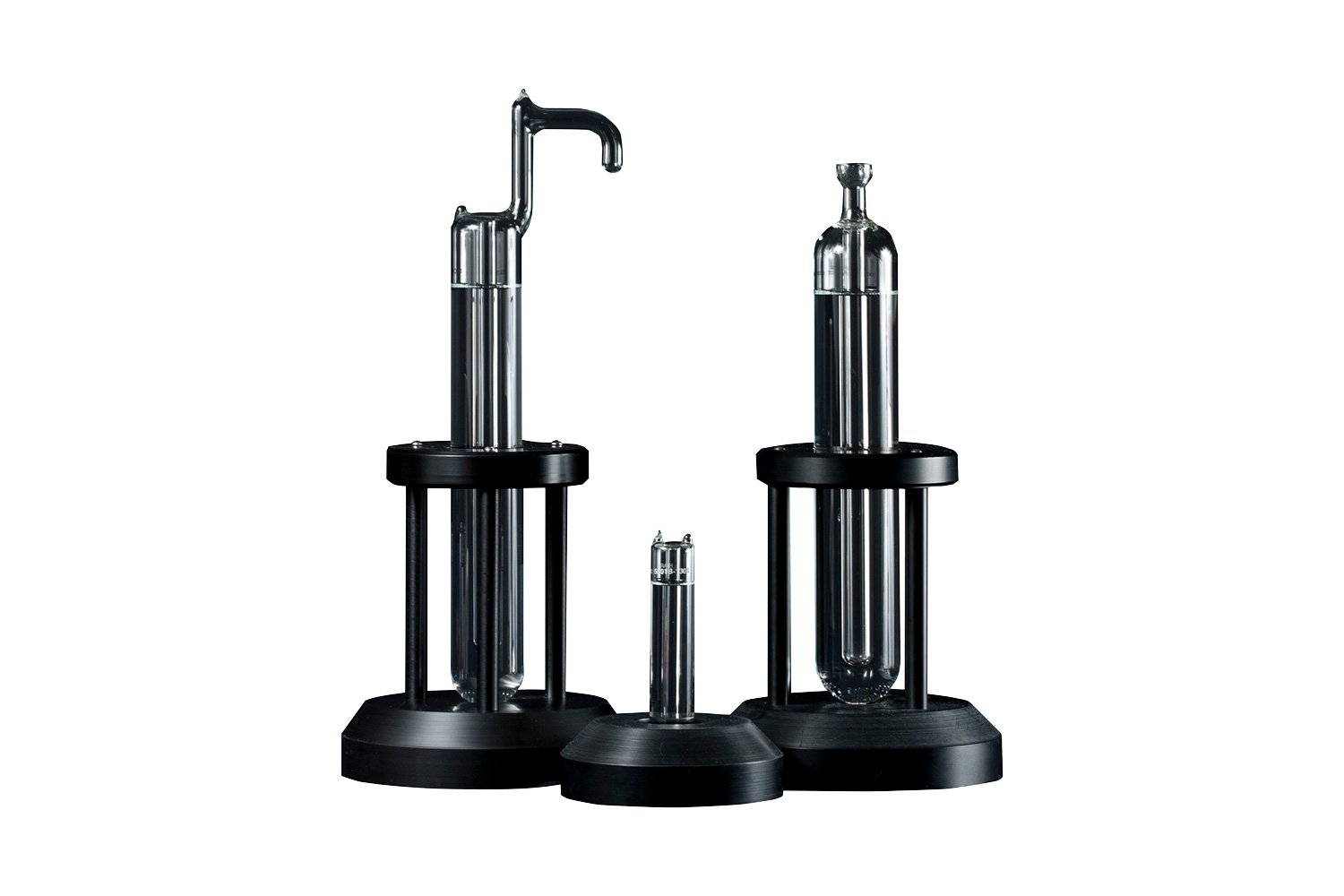
Five TPW cells, with different sizes and shell materials, are shown in Fig. 1. Types A, B, C, and D are made of high-quality Pyrex glass. Type E is made of 304 stainless steel (SS). Many national temperature laboratories around the world use Type A. Type B follows the design of the original NBS cell, which had a glass support arm. The arm can be used as a McLeod gauge to check the remnant gas in the cell. Some users prefer this design because they can use the arm as a handle to carry the cell or to position it within an ice bath.
Type D is the same as Type A excepting for its well size, which is 13.6 mm rather than 12 mm. Types C and E were developed mainly for secondary and industrial calibrations. They have smaller sizes that are easy to handle, accommodate shorter sensors, and can be maintained in automated portable maintenance apparatus. We found stainless steel to be a poor material for the TPW cell and will discuss this point in detail.
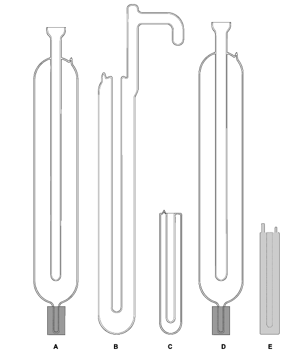
Fig. 1 Five designs of TPW cells
Fabrication of TPW Cells
Meticulous cleaning of all parts is extremely important for manufacturing TPW cells. Two years ago, a more elaborate cleaning procedure was adopted. The new procedure has proven to be a very effective. The main points of this procedure are summarized here:
- Soak the Pyrex shell in a special detergent solution for a few days. Then fill the shell halfway with the same solution and shake it for about 10 minutes.
- Flush the shell with deionized water.
- Fill the shell completely with a special acid solution for ten minutes.
- Flush the shell with deionized water and then again with high-purity water (with resistivity higher than 17.8 MΩ•cm) for many hours.
- Flush the shell with high-purity water steam for many days.
- Rinse the shell with double-distilled high-purity water.
Water from a purifying system is double distilled directly into the Pyrex shell immediately after the cleaning procedure. The cell is then connected to a powerful glass high-vacuum system, which we started to use four years ago. A 4-inch glass diffusion pump and a mechanical pump are used in the system. The pumping speed of the system is 300 liters per second and the ultimate pressure is lower than 1 x 10 –7 torr (1.3 x 10 –5 Pa).
The Pyrex shell is then connected to the system through two water-cooling condensers, a high-vacuum valve, and three liquid nitrogen traps. The traps and condensers remove oil vapor in the TPW cell from the pumps and prevent water vapor from getting into the pumps. The cell should be pumped for several hours at about 60°C.
The water in the cell begins to boil immediately after pumping and any gases dissolved in the water are pumped out. Remnant gases are removed along with the water vapor. This pumping procedure minimizes the remnant gas. As soon as the water level in the cell drops to the desired level, the cell should be sealed with a torch.
We originally thought a single distilling would be adequate if we started from high-purity water with resistivity higher than 17.8 MΩ•cm. Later we found a very small but measurable difference (less than 0.1 mK) between the cell filled with single distilled water and the cell with double distilled water.
Cell Tests
Two TPW cells (5901A-7-1022 and 5901A-7-1024), were manufactured according to the technique described. They were sent were sent to NIST for certification. Direct comparisons of the two TPW cells were made against NIST reference cells at NIST. Fig. 2 is copied from NIST’s “Certificate of Analysis.” The difference between cell 5901A-7-1022 and NIST’s reference cell was 0.01 mK. For cell 5901A-7-1022, the difference was 0.005 mK. NIST assigned an expanded uncertainty (k=2) of 0.04 mK on the realized value of their reference cells.
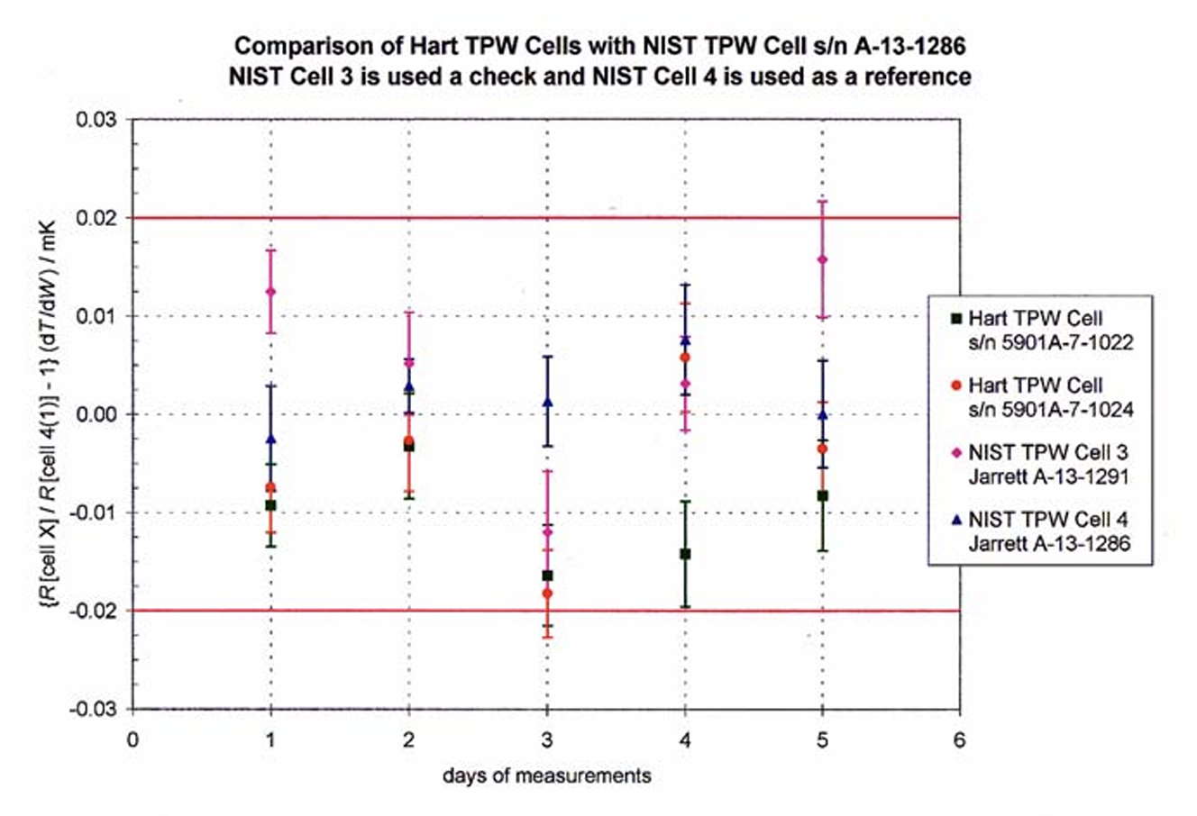 Fig. 2 Comparison of Hart TPW cells with NIST Cell A-13-1286. NIST Cell 3 is used as a check standard and NIST Cell 4 is used as a reference.
We have performed many comparison tests among TPW cells in our laboratory over the past few years. One example of the results is shown in Fig. 3. TPW cell 1047 was compared against the TPW cell 5901A-7-1024 in September 1999. The average difference between them was within 0.01 mK.
We even found out that more recently manufactured TPW cells had a little higher equilibrium temperature compared to Cell 5901A-7-1024. Since all major error sources in TPW cells (including impurities in the water and remnant gas in the cell) lower the equilibrium temperature within the cell, higher equilibrium temperatures indicate better quality.
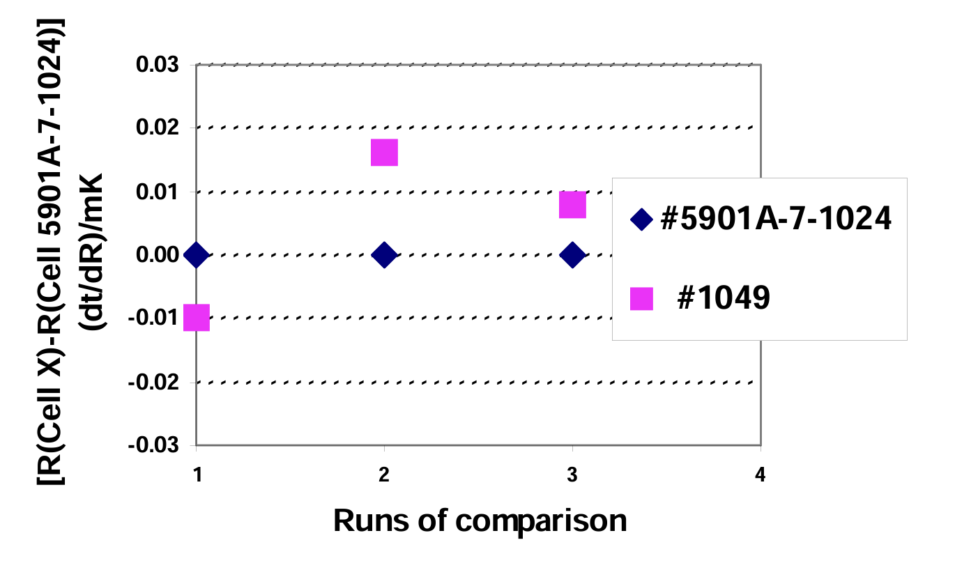 Fig. 3 Direct comparison between TPW cell 1047 and TPW cell 5901A-7-1024
TPW Cells for Secondary and Industrial Calibration
The realization of the triple point of water in traditional cells requires dry ice or liquid nitrogen to create an ice mantle and a fluid bath or ice dewar to maintain the phase equilibrium state within the cell. An automated device for realizing the triple point of water would, of course, be attractive for secondary and industrial level calibration work. Furthermore, many short probes that are difficult to calibrate in a traditional cell require a shorter TPW cell.
A small Pyrex TPW (SP TPW) cell with an outside diameter of 30 mm and a total length of 165 mm was developed to simplify TPW realizations for industrial and secondary calibrations (Fig. 1, Type C). The manufacturing procedure of the SP TPW cell is virtually identical to that of traditional TPW cells.
A portable apparatus with thermo-electric cooling modules was developed for automatically realizing the triple point and maintaining its phase equilibrium state. The apparatus was designed with built-in programming for fast and easy operation. Three pre-set temperatures are built into the unit’s controller: 5°C (melt mode), near 0°C (maintain mode), and –4°C (freeze mode). Operation is extremely simple. Enter the “freeze” mode through the front-panel buttons. When the apparatus alerts you (about ten to twenty minutes later), remove the cell from the apparatus and give the cell a light shake. The water in the cell—supercooled at a temperature of –4°C— immediately begins to freeze. Fine needle-crystals (dendrites) of ice appear uniformly throughout the cell and approximately 5% of the water freezes in a few seconds. Return the cell into the apparatus and change the program mode to “maintain.”
Generally, the plateau in such a cell will last for about thirty hours. A typical freezing curve is shown in Fig.4. The temperature in a SP TPW cell, newly frozen in this manner, is typically about 0.001°C below the triple point of water. It may take up to ten hours to raise the temperature to within 0.2 mK of the final equilibrium temperature. Creating an “inner melt” around the central well (by inserting a glass rod at room temperature) can expedite this warming process.
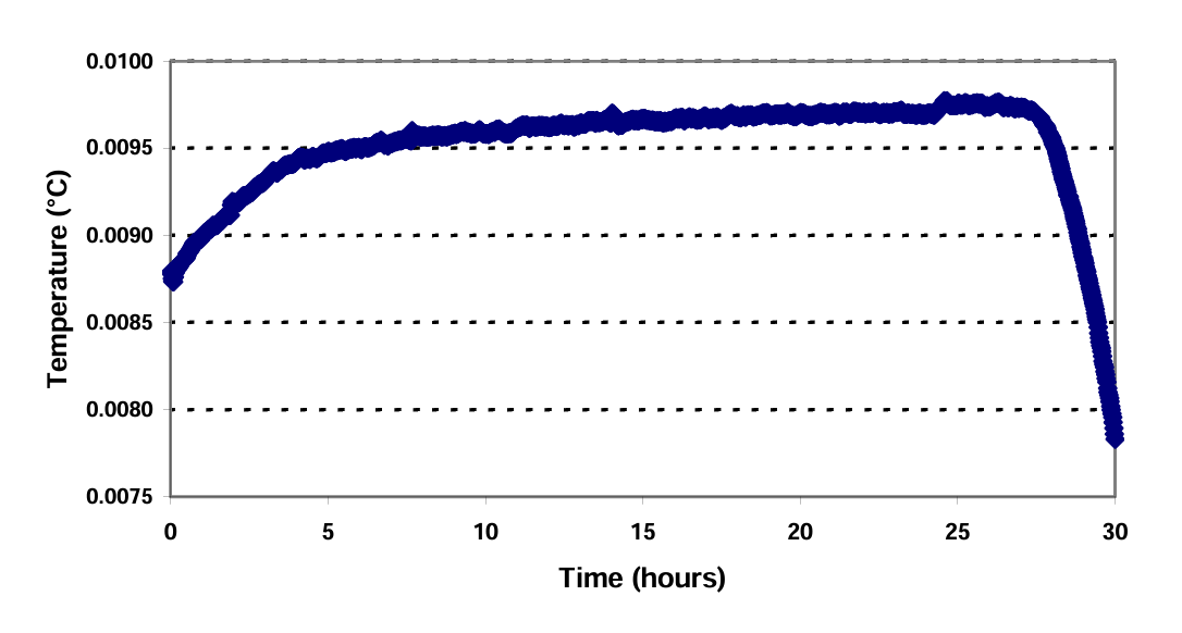 Fig. 4 A typical freezing curve in a SP TPW cell
The equilibrium temperature in a SP TPW cell maintained in the above-described portable apparatus was compared to that of a regular TPW cell (1087) using an SPRT. Before the comparison began, the SP TPW cell was aged for ten hours after realization. We alternated five measurements in the cells—three in the regular cell and two in the SP TPW cell. The results are shown in figure 5. The average difference between the two cells was within 0.0001°C. If an uncertainty from 0.0002°C to 0.0005°C is required, we suggest freezing the SP TPW cell in the late afternoon and using it the next day. If an uncertainty of 0.001°C is satisfactory, the cell may be used immediately after freezing the ice in the cell.
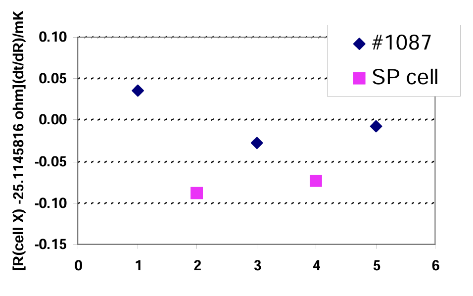 Fig.5 Comparison between equilibrium temperatures in a SP TPW cell with a portable apparatus and a regular TPW cell (S/N 1087)
Though excellent for laboratory use, Pyrex is too fragile for many industrial applications; so, we developed metal-cased TPW cells (Fig.1, Type E). 304 stainless steel was tried first. The length of the cell is 127 mm (5”), so it can be used in dry-wells, Micro-Baths, and small portable apparatus. The immersion depth is about 100 mm.
Because of the relatively short immersion depth, a close fit between the probe and the re-entrant well of the cell is important. The diameter of many PRT probes is 6.35 mm (1/4”) while the diameter of many popular metal sheathed SPRTs is 5.56 mm. Therefore, two diameters of re-entrant wells were used for these probes—6.64 mm for 6.35 mm probes and 5.84 mm for 5.56 mm probes.
Realization of the TPW using these mini metal-cased cells is very simple. Many varied apparatus can be used, including Micro-Baths, dry-wells, and small portable apparatus. Cool the cell to about –4°C for a few minutes in a bath or dry-well. Remove the cell from the apparatus and give the cell a shake. The water in the cell (supercooled at a temperature of –4°C) immediately begins to freeze. Return the cell into the apparatus and maintain the apparatus’ temperature close to 0°C.
An alternative method for freezing the cell is as follows. Pre-cool the cell to approximately 0°C. Add a few drops of liquid nitrogen into the re-entrant well of the cell. Sequentially insert two metal rods, pre-cooled to the liquid nitrogen temperature, into the well and leave each rod in the cell for two minutes.
An equilibrium temperature curve recorded in this way for a newly manufactured cell (31004) is shown in Fig.6. An SPRT was measured in a traditional TPW cell (1022) before the curve started and at about the 29th hour of the curve. The temperature differences between cell 1022 and the mini SS cell 31004 were well within 0.5 mK. One year later, however, we repeated the measurements and found the differences between them had become much larger (> 2 mK). Hydrogen generation in the cell might cause this problem when water is in direct contact with stainless steel for a long time (7,8).
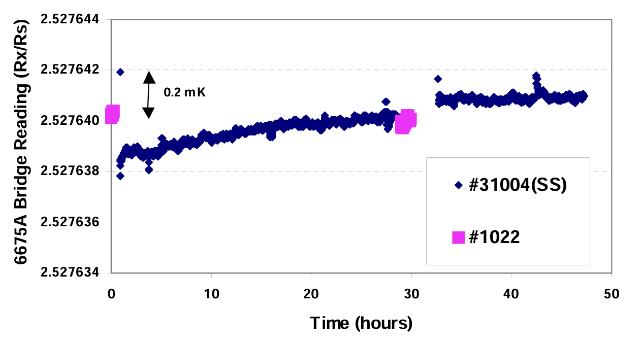 Fig. 6 Data from a mini SS TPW cell compared with a traditional TPW cell
The Effects of Isotopic Composition of the Water
As we know, the equilibrium temperature in a TPW cell is dependent on the isotopic composition of the water in the cell—e.g. a decrease of 10 µmol of 2H per mole of 1H corresponds to a decrease of temperature of the triple point of 40 µK. The definition of the Kelvin — the unit of thermodynamic temperature—does not specify the isotopic composition of the water used to define the triple point of water. “Supplementary Information for the International Temperature Scale of 1990” states that the water used in the TPW cell should have substantially the same isotopic composition as ocean water. Natural waters show a wide variation in their isotopic composition. Furthermore, the purification process of water might change the isotopic composition to some extent. So, for the highest accuracy, it is necessary to know the actual isotopic composition of the water in a TPW cell.
A TPW cell manufactured according to the technique described in the paper was sent for an isotopic composition analysis and the results obtained are as the follows. (All measurements are with respect to VSMOW, Standard Mean Ocean Water.)
δ 2H (‰): -99.0; δ 18O (‰): -11.87
Isotope ratios based on the above results were:
2H/1H = (140.3 ± 1.0) ppma
17O/16O = (370 ± 5) ppma
18O/16O = (1981.3 ± 1.0) ppma
(1 ppma is 1 atomic part per million)
The isotopic composition of water in our TPW cell is typical to continental surface water.
Based on the information gathered, we made following three improvements in manufacturing TPW cells:
- A more elaborate cleaning procedure.
- Double distilled, high-purity water was used to fill the TPW cells instead of single distilled water.
- A more powerful vacuum system and a new pumping procedure was used.
Two TPW cells manufactured according to the improved technique were sent to NIST for certification. The differences between those two cells and NIST reference cells were within 0.01 mK.
Reference
- 10th General Conference on Weights and Measures (10th CGPM, 1954)
- 13th General Conference on Weights and Measures (13th CGPM, 1967-1968), Resolutions 3 and 4, p. 104
- Preston-Thomas, H. “The International Temperature Scale of 1990 (ITS-90),” Metrologia, Vol. 27, p. 3–10 (1990); ibid. p. 107
- R. Pello, R. Goebel and R. Kohler, “Report on the International Comparison of Water TriplePoint Cells,” Rapport BIPM-96/8, Document CCT/96-1 (1996)
- National Institute of Standards and Technology, Certificate of Analysis (International Temperature Scale of 1990), Water Triple Point Cell, Hart Model 5901A, Serial Number 5901A-71024, Test No. 836/798004-98 (1 July 1998)
- National Institute of Standards and Technology, Certificate of Analysis (International Temperature Scale of 1990), Water Triple Point Cell, Hart Model 5901A, Serial Number 5901A-71022, Test No. 836/798004-98 (1 July 1998)
- C. A. Busse et al, Paper No. 4-2, First International Heat Pipe Conference, Stuttgart, Germany, October (1973)
- Y. Hermier and G. Bonnier G., “A Water Triple Point in a Multicompartment Cell,” Thermal and Temperature Measurement in Science and Industry (Institute of Measurement and Control, London), 3, TEMP/MEKO 87, Sheffield, UK, 33-39
- BIPM, Supplementary Information for the International Temperature Scale of 1990 (1990)
- Stable Isotope Laboratory, Water Isotope Report (Client Reference: 53039C-10, 06 December 2000)