It’s not hard to locate electrical wires during construction — but in a finished structure, finding those wires is a very different story. A well-designed wire tracer can be one of your most important time- and money-saving investments.
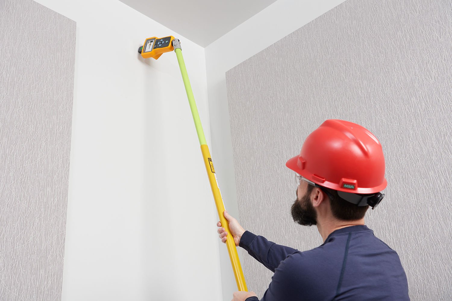
Here’s how to set yourself up for success when using an advanced wire tracer.
1. Make the connection
The first step is connecting the transmitter, either through a test lead or current clamp. For most applications, a direct test lead connection will give you the best results.
- Connect the red and green test leads to the transmitter.
- Connect the red test lead to the hot wire on the load side of the circuit (whether or not the circuit is energized or de-energized).
- The last — yet most important for accurate results — step is to connect the green test lead to a separate ground, depending on the type of circuit the wire you want to trace is on. If the green lead isn’t grounded properly, or if it’s connected to the same circuit as the hot wire, you can get signal cancellation.
- If the wire is not connected to a ground fault circuit interrupter (GFCI) or a residual current device (RCD, commonly found outside the U.S.):
- Connect the green test lead to a separate ground such as a metal water pipe, a metal grounded structure of the building, a grounded screwdriver, or a grounded stake.
- For a wire connected to a GFCI outlet:
- Make sure the circuit is energized.
- Remove the protective receptacle wall plate.
- Connect the red test lead to the screw of the hot wire.
- Connect the green test lead to a separate ground.
- If the wire is connected to a GFCI breaker:
- Check that the circuit is de-energized to avoid tripping the breaker.
- Locate the closest connection to the breaker or fuse panel that is on a different branch of the same circuit that is connected to the same GFI breaker.
- Connect the green test lead to the neutral wire of the identified closest connection.
- For a wire connected to an RCD:
- Locate the closest connection to the breaker or fuse panel that is on a different branch of the same circuit that is connected to the same RCD as the line or phase wire.
- Connect the green test lead to the neutral wire of the identified closest connection.
- If the wire is not connected to a ground fault circuit interrupter (GFCI) or a residual current device (RCD, commonly found outside the U.S.):
If a direct connection on a bare conductor isn’t available, an advanced wire tracer will also be able to use a current clamp on low impedance closed circuits. Because it doesn’t have a direct connection to a conductive wire, however, the signal isn’t as strong as a direct connection. The receiver may not detect its signal if the clamp is far away.
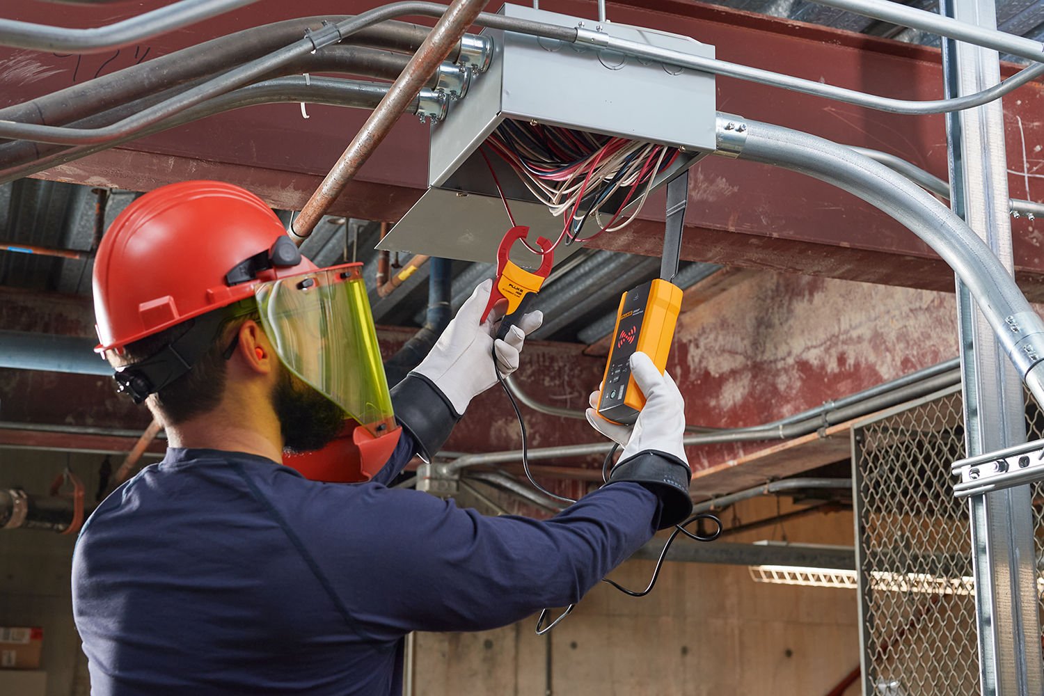
- To connect a current clamp, connect the test leads to the transmitter, then close the clamp around the wire you want to trace. To increase signal strength, you may be able to wind a few turns of the conductive wire around the clamp.
- For signal cables and de-energized wires or loads, you may also be able to temporarily ground the circuit on both ends in order to perform your trace.
2. Set up the transmitter
Once you’ve made the connections, the next step is to set up the transmitter itself.
- Turn on the transmitter. Depending on the voltage present, an advanced wire tracer will automatically select energized or de-energized mode.
- A tool designed with your safety as a priority should have a clear indicator that confirms whether the signal is energized or de-energized. It should also give you a clear warning or alarm if it detects an energized over-voltage signal — which means you must disconnect from the circuit immediately.
- An advanced wire tracer will give you a choice of signal modes.
- Most applications will use the High mode.
- For applications that require precise tracing, use Low mode to generate a low signal that reduces coupling to nearby wires and objects.
- Use Loop mode to trace de-energized wires in a closed circuit, such as shorted or shielded wires, or when using the current clamp.
- Always be aware of grounding issues to avoid incorrect results.
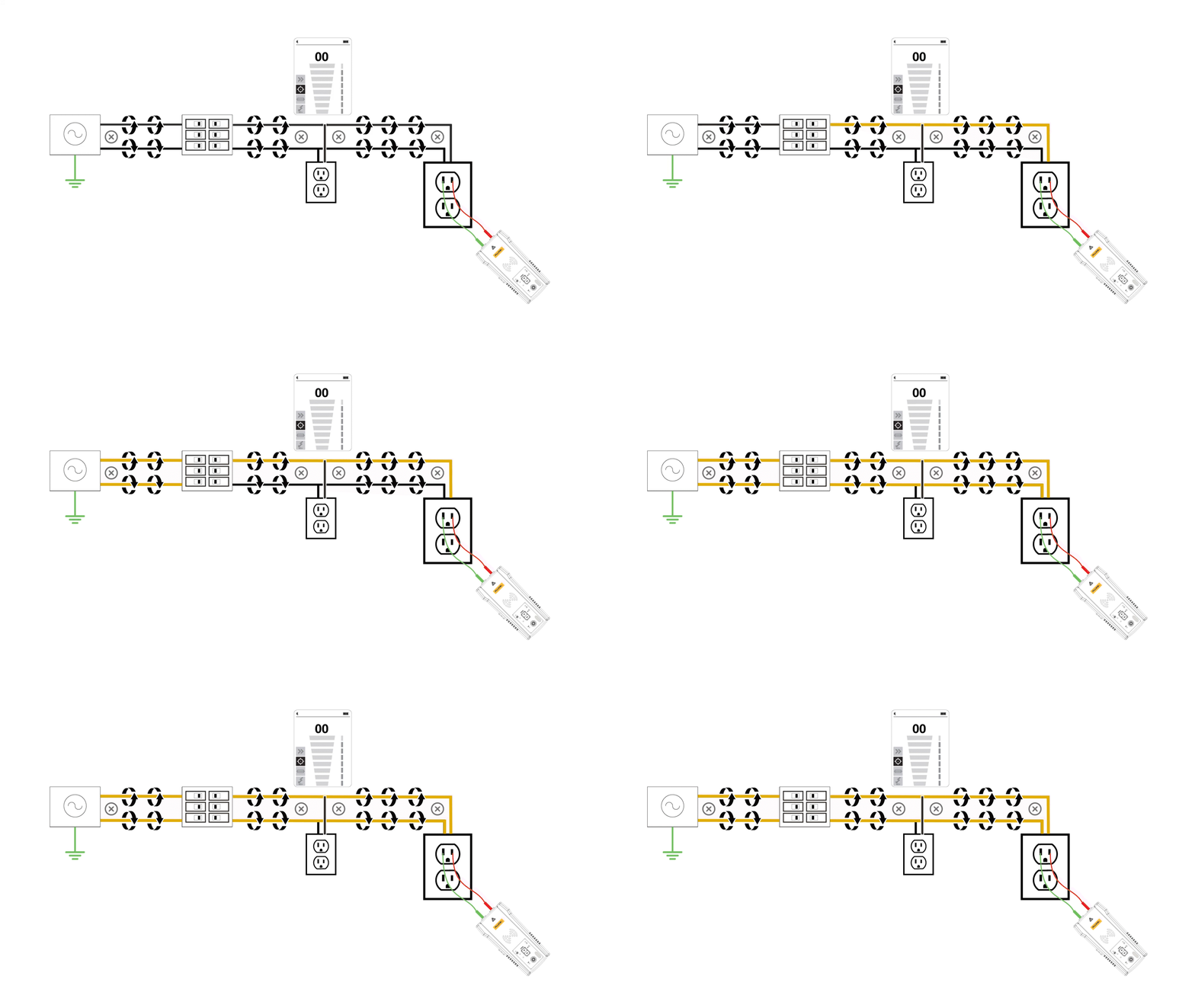
- If you connect the transmitter to two adjacent wires on the same circuit (hot and neutral wires on a Romex cable, for example), you’ll get signal cancellation: the signal will travel in one direction through the first wire and then return in the opposite direction through the second.
- When you make connections, be sure to connect the green test lead to a separate ground (a metal water pipe, the grounded metal structure of the building, or a grounded stake) to avoid inaccurate signals from signal coupling.
3. Trace with the receiver
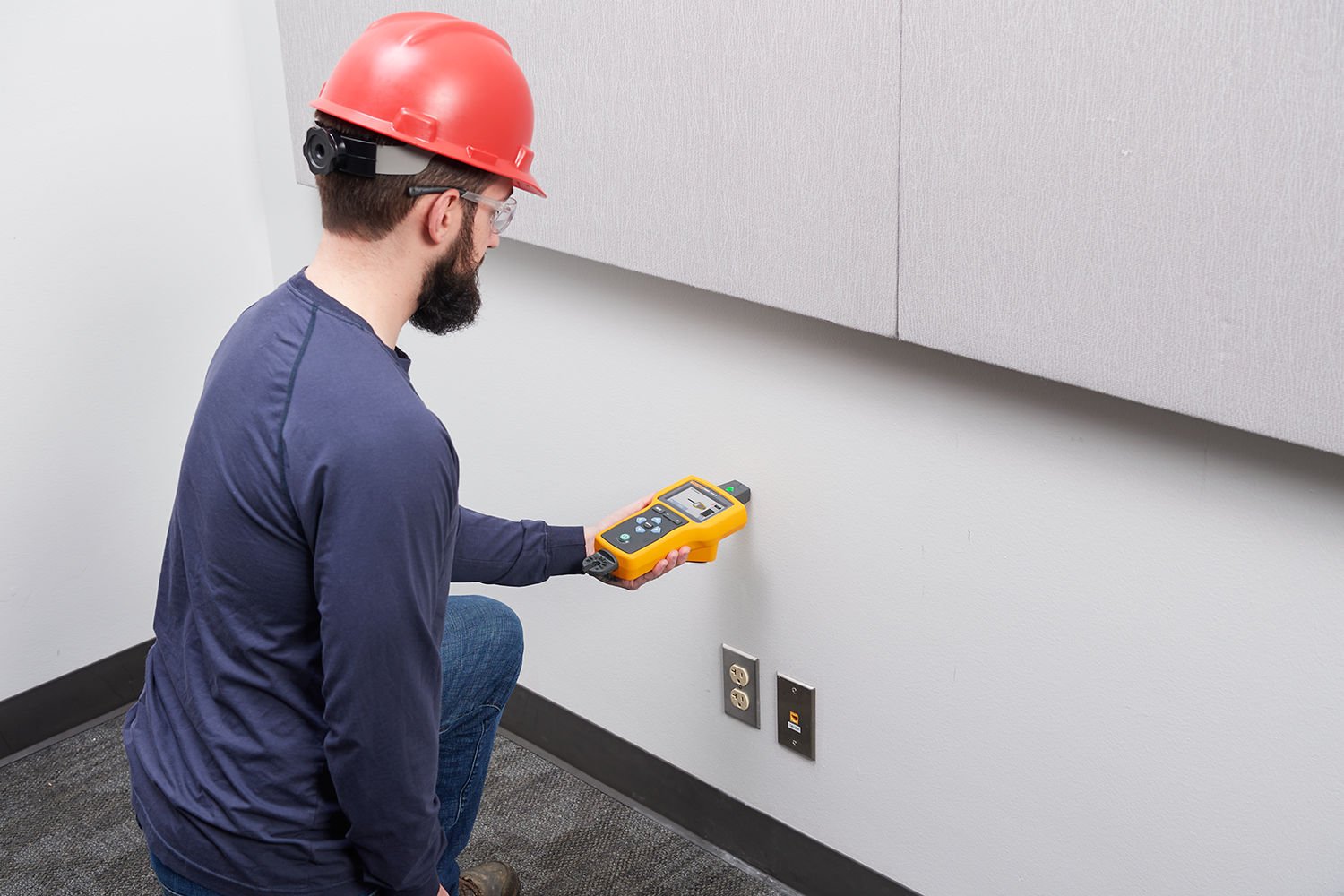
With the transmitter connected properly and activated, you’re ready to trace the wiring on the circuit. Remember to keep the receiver at least 3 feet away from the transmitter to minimize signal interference.- Select the mode you want to use. Most receivers have a mode to scan, another mode for more precise signal detection, a mode for identifying a breaker, and a mode for non-contact voltage detection (without the transmitter).
- Move the receiver along the wall to find the highest signal level, which indicates the presence of the wire. Most receivers have a feature, such as a groove on the sensor, that guides you in aligning parallel to the wire.
- If a signal is detected, you should see a strong signal on the strength scale. If there’s no signal detected, you can increase or decrease the sensitivity to identify the line or phase wire from the neutral line.
- Adjust the sensitivity to keep signal strength at about 75% of the scale (or as recommended by the manufacturer) so that you have a clear indication when the receiver detects the wire. If you adjust to the minimum and the signal is still too high, turn the transmitter to Low mode.
- Continue following the signal with the receiver until you reach the end of the wire or a connection to other equipment, marking locations as you go. Repeat to trace all the wiring you need to find. Record your results for future reference and troubleshooting.
4. Identify breakers
To make identifying breakers faster and easier, use the receiver to detect the signal from your transmitter.
- Align the sensor perpendicular to the breaker.
- Scan each breaker or fuse for longer than one second in repeated passes, until you’re sure that the display identifies a strong signal for only one breaker or fuse.
- Record your results and mark the breakers for future reference.
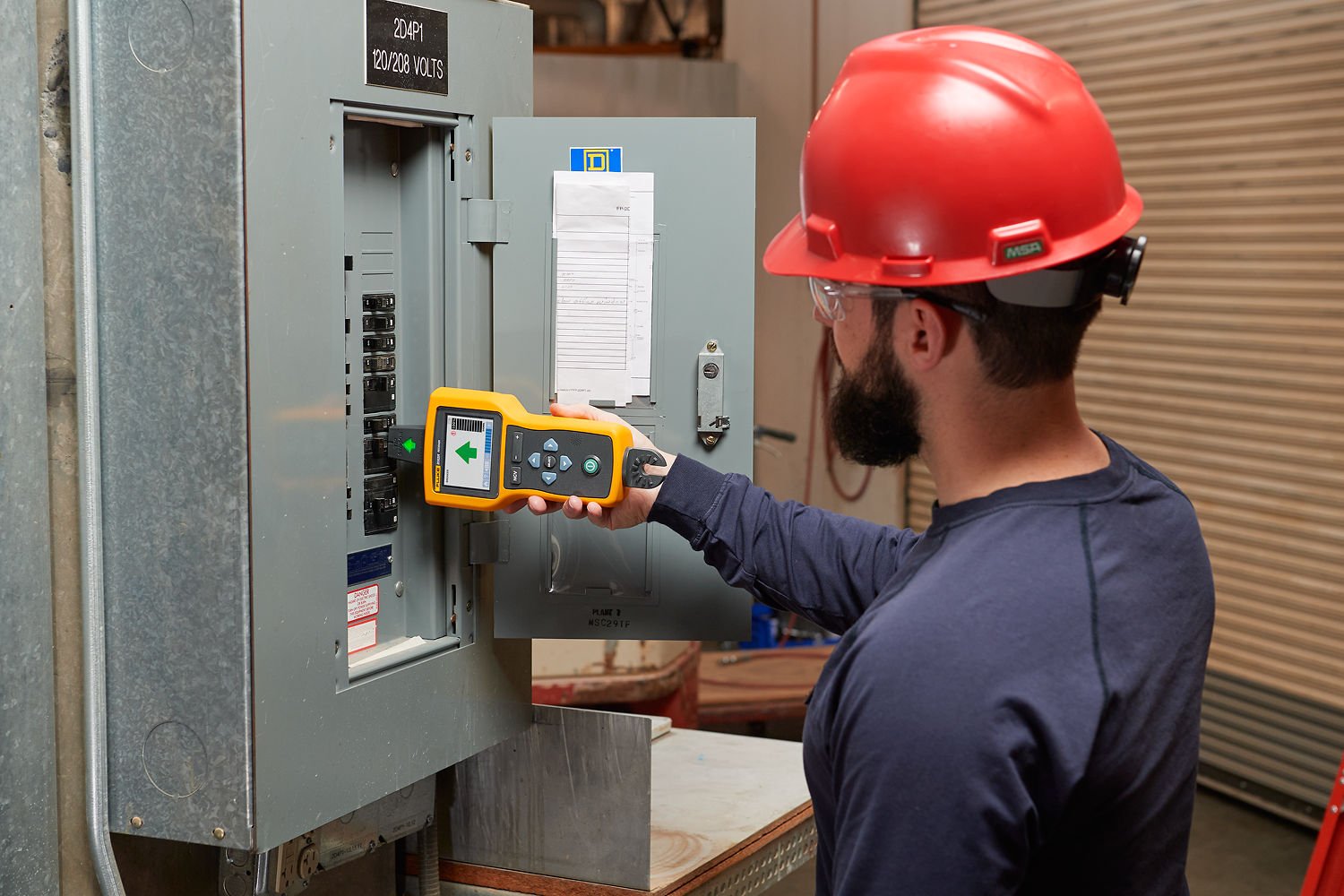
A good wire tracer gives you an advantage
Wire tracing is as much an art as it is a science. There are so many wiring scenarios and so many variables that good results can be hard to get.
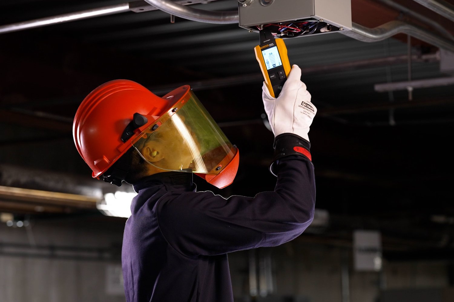
A well-designed wire tracer gives you advantages — like a higher category and voltage rating, more adjustable sensitivity levels, and different transmitter output frequencies — that can help you stay safe and obtain the most accurate results possible in just about any situation. Master setting it up and using its advanced features, and your colleagues (and clients) might even start to think you can see through the walls.