Many applications require leak detection. Among the more well-known ones include compressed air systems used in many applications and commonly employed in manufacturing plants.
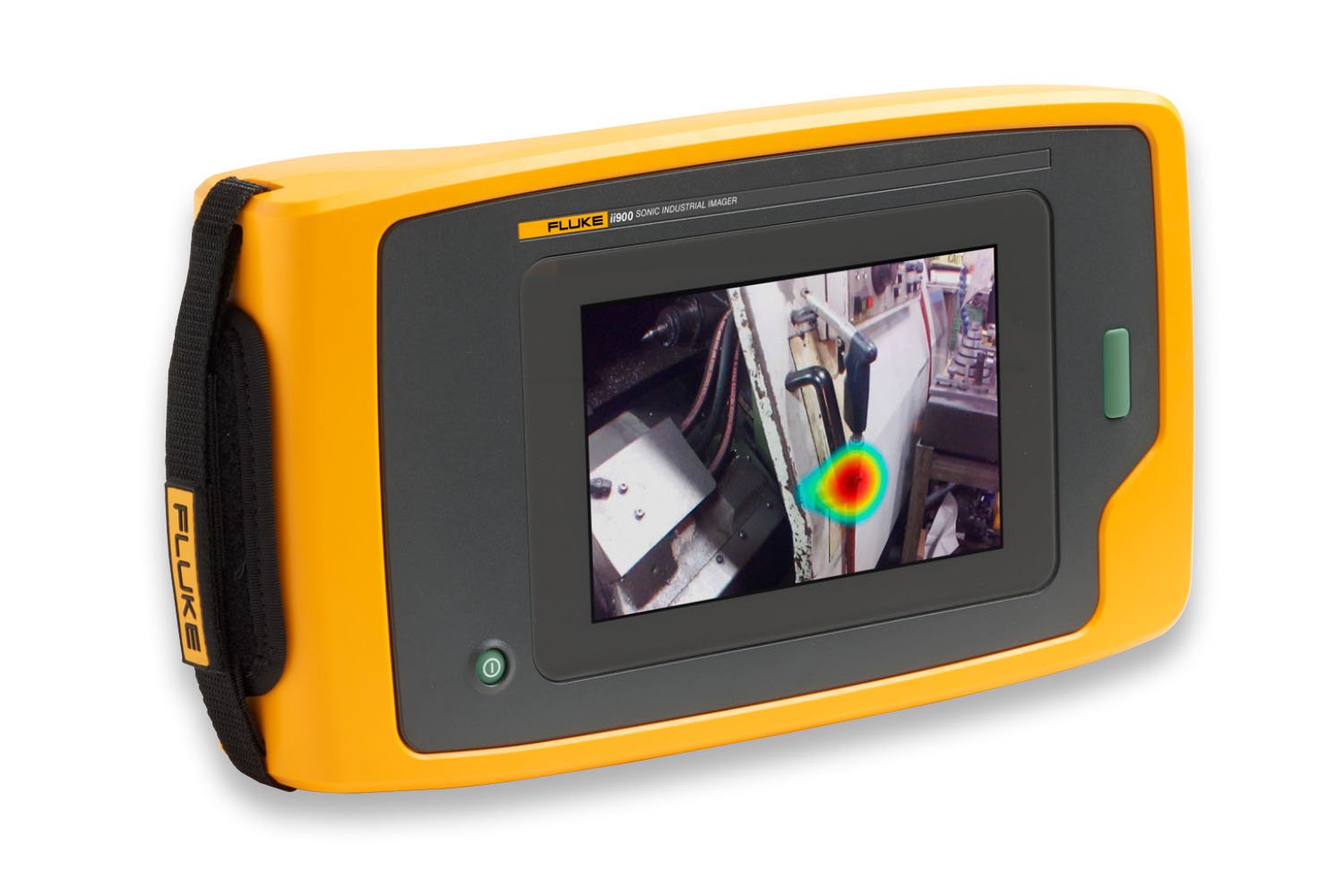
Refresher on the operation of the Fluke ii900 and ii910 acoustic imagers
The Fluke ii900 Industrial Acoustic Imager and Fluke ii910 Precision Acoustic Imager use 64 microphones arranged in a specific array pattern. It has a visible camera in the middle of the array providing an image of the scene. The device uses complex algorithms to generate a sound map or image of the sound sources and then overlays the generated sound map on to the image. Depending on the sound source’s position concerning the ii900/ii910 field of view, the sound is received slightly different times by each microphone. The inter-microphone time differences allow locating the sound source’s position. If the sound is coming from the right side of the device, the microphones on the right side of the array will receive the sound a fraction of a second earlier than the microphones on the left side. The Fluke ii900 and ii910 acoustic imaging cameras would display the image for that sound on the right side of the screen.
How do the Fluke ii900 and ii910 acoustic imaging cameras detect leaks?
When a leak occurs in a pressurized system, the escaping gas (air) molecules will cause turbulence, which causes rapid changes in pressure and flow velocity. These changes may be transmitted as sound waves. The Fluke ii900 and ii910 acoustic imaging cameras can detect the location and the intensity of these sound waves.
Compressed air leaking to the ambient atmosphere creates broadband noise in both the audible and the ultrasonic frequency range [Eret, Holstein]. In industrial compressed air systems, narrowband (centered around 40 kHz) ultrasonic sensors is a widely used tool for leakage localization. However, using a narrowband ultrasonic sensor brings some limitations.
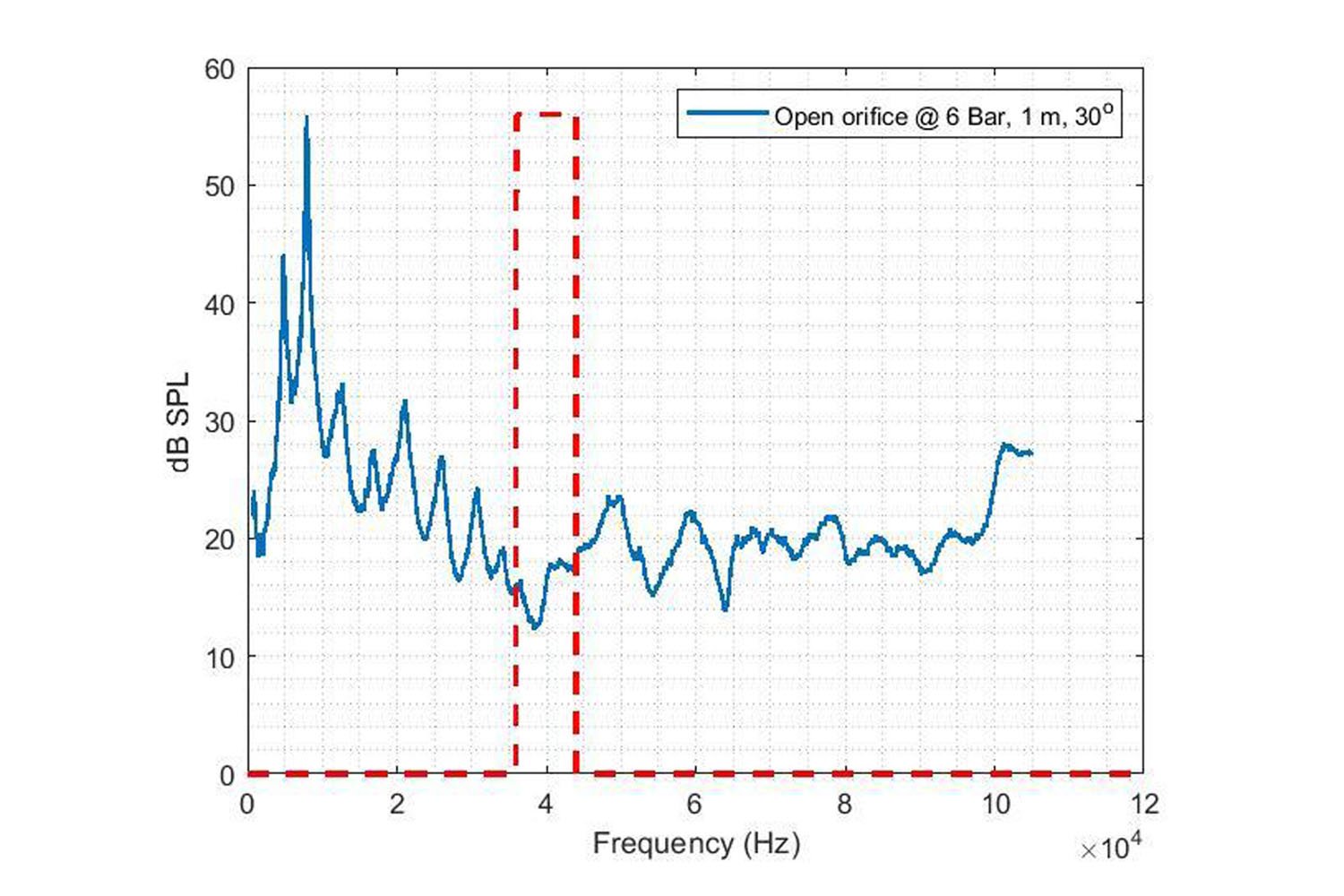
The distance between the leak and the measurement device and the measurement angle are essential factors that contribute to the ultrasonic sensors’ effectiveness: First, the high-frequency sound is rapidly attenuated by atmospheric absorption [Wolstencroft]. Second, the sound pressure level generated by a compressed air leak varies with the measurement angle [Wolstencroft]. Additionally, noisy environments are known to degrade the performance of the narrowband ultrasonic sensors [Eret]. Utilizing broadband sensors that operate both in the audible and ultrasonic frequency ranges allows the user to compensate for the limitations mentioned above. Provided flexibility in frequency range increases the robustness of the leak detection system. For instance, it can be seen in Figure 1 that the compressed air leaking out of open orifice under system pressure of 6 Bar generates a broadband noise. Figure 1 shows that the frequency region with the largest measured sound pressure level is in the audible range. In contrast, the sound pressure level measured in the frequency range of 35 – 45 kHz (red dashed lines in Figure 1) is noticeably lower than the rest of the frequency spectrum.
There are a limited number of studies that investigate the frequency characteristics of compressed air leak sounds. In the study of Holstein et al. (2016), frequency spectra of compressed air leak measurements with systematically increased flow rates were presented (see Fig. 2 in Holstein). The leak source was an open round orifice, and the measurements were taken from a 20 cm distance from the source. The frequency spectra show that the larger the flow rates get, the energy above 50 kHz increases. For the largest flow rate measured in the experiment, the frequency spectrum shows a peak of around 80 kHz.
Factors affecting leak detection
Factors that affect leak detection are discussed separately in the present section. It should be noted that the factors explained in the present section interact with each other and should be considered as single components of a broad complex phenomenon.
Leak source factors
- System pressure: Generally, the greater the system pressure, the greater the leak leading to higher sound intensity, making detection easier.
- Flow rate: Like pressure, the higher the system’s flow rate, the greater the leak leading to a higher sound intensity measured at the leak position. Higher sound intensity makes acoustic detection easier.
- Size and shape of the orifice: The size and shape of the orifice need to be considered together. When we consider the wide variety of potential air leaks, it soon becomes challenging to provide a guideline on the effect of shape and size on leak detection. This list shows some of the potential leakage sources. Both the size and the shape of the orifice differ for each item on the list Air hoses and air hose connections or couplings:
- Worn disconnects or disconnects missing O-rings
- Filters, lubricators, and regulators, if improperly installed
- Open blow-offs
- Open condensate traps
- Leaking or botched drains
- Failed or inferior quality thread sealants or incorrectly applied thread sealants
- Control and shut-off valves
- Worn out seals or gaskets
- Old or poorly maintained pneumatic tools
- Idle or unused machine or production equipment with air input
Fluid properties
The properties of the fluid affect the generated sound as it escapes from the leak.
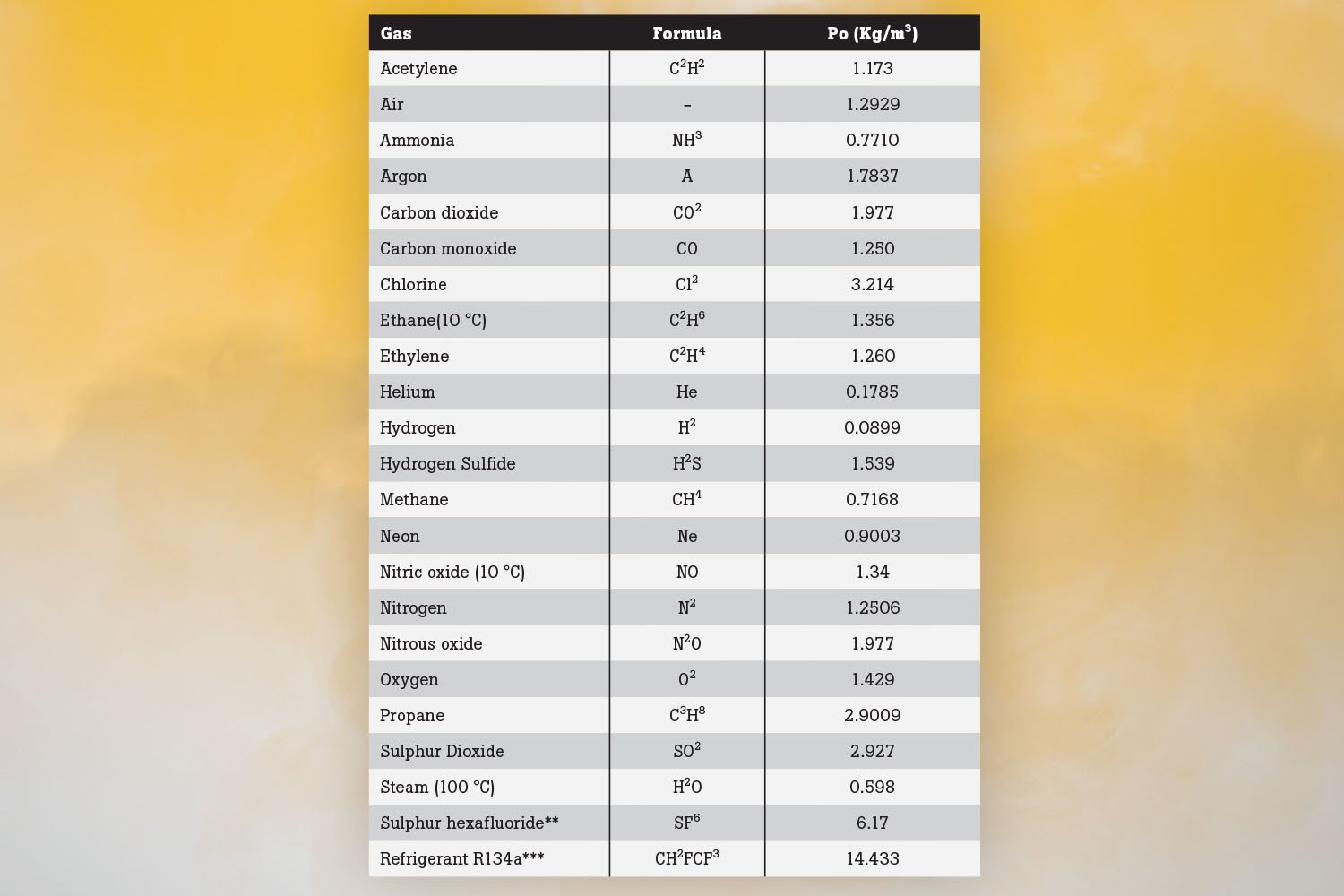
- Density: Table 1 shows the density of gasses in Kg/m3 at 0°C and one atmospheric pressure. The density of gas has an impact on the sound intensity of the leak. For example, Helium’s low density means that, when compared with the compressed air, assuming the same flow rate and pressure, the sound pressure levels measured at the leak position will be lower. Field experience confirms that detecting a Helium leak is challenging.
- Viscosity: The viscosity of the gas affects the sound pressure level at the leak position. However, its impact will be less than that of density.
- Ambient temperature: We must consider the ambient temperature in both the leak source and the path. For the leak source, the ambient temperature will affect the density and the viscosity. Both factors will alter the sound pressure level at the leak position. As the ambient temperature increases, the molecule kinetic energy increases, leading to an increased sound intensity at the leak.
- Ambient pressure: Ambient pressure will have a direct bearing on the density of a gas. A reduction in ambient pressure will lead to lower density, which will reduce the sound intensity at the leak.
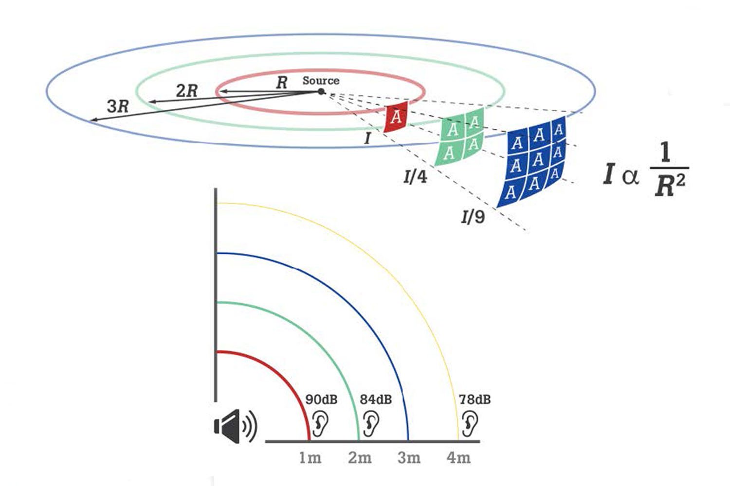
- Distance from the leak to camera: The measuring distance affects the measured sound pressure level. As the sound propagates in all directions from the source, its intensity diminishes with distance.
- Ambient temperature: Changes in ambient temperature can alter both the density of gases and the viscosity. Both, in turn, affect the speed of the sound as it travels through the medium. As the temperature increases, the sound travels faster. The ambient temperature change is one of the mechanisms that affects the amount of acoustic energy absorbed by the atmosphere. For low frequencies and short distances, the impact of temperature on air absorption is negligible [Harris]. However, for very high frequencies and long distances, the sound pressure level can be decreased noticeably [Vladišauskas].
- Humidity: The second mechanism that impacts the sound pressure level due to air absorption is the humidity. As ambient temperature effects, under normal conditions, humidity on sound pressure level is negligible[Harris]. The impact is noticeable for very high frequencies and high humidity levels [Vladišauskas].
- Ambient pressure: The ambient pressure does not impact sound pressure level in an ideal gas approximation since both the air density and gas pressure have similar but inverse effects on sound speed. The two contributions cancel out. Therefore, no difference is expected between the leak position's sound pressure level and at the measurement position due to the ambient pressure.
What leak properties do Fluke ii900 and ii910 acoustic cameras measure?
The Fluke ii900 and ii910 acoustic imaging cameras reveal the leak type and estimate the flow rate of the leak based on acoustic input. A set of laboratory experiments was designed and conducted for developing the leak type classification and flow rate prediction algorithms.
Leak type classification in Fluke ii900 and ii910
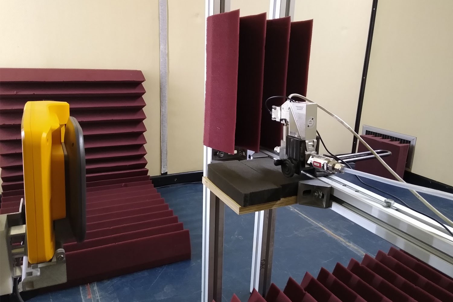
The Fluke ii900 and ii910 acoustic imaging cameras classify the captured acoustic leak data based on where it occurs: Hose, open-end, quick-connect, and threaded coupling. Four classifications, the four leak types, were installed at the end of a compressed air tubing system, and the acoustic measurements were conducted in a semi-anechoic chamber. Two examples of the experimental setup are presented in Fig. 3 and Fig. 4. The fittings that formed the four leak conditions for the experiment are shown in Fig. 5.
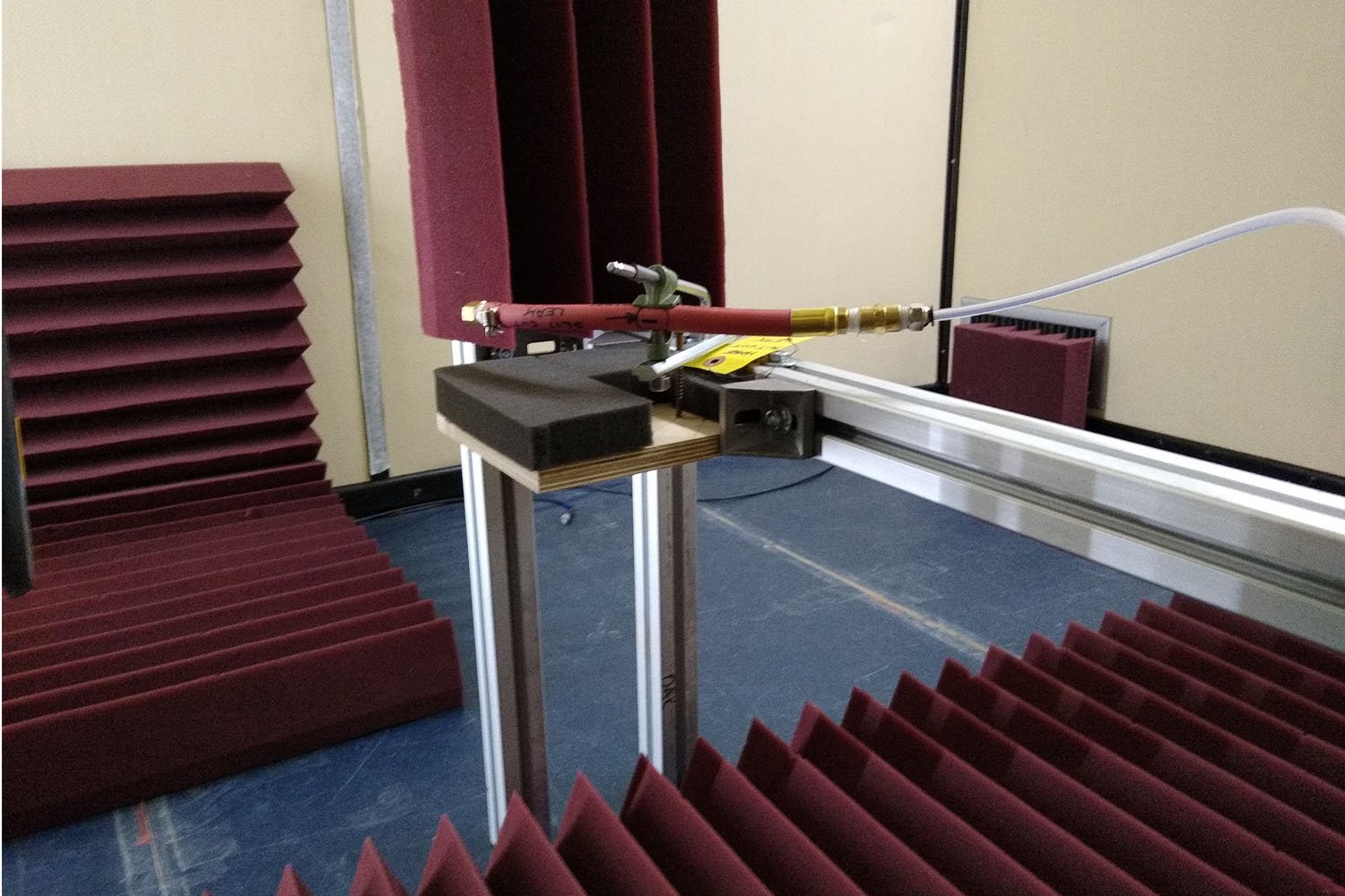
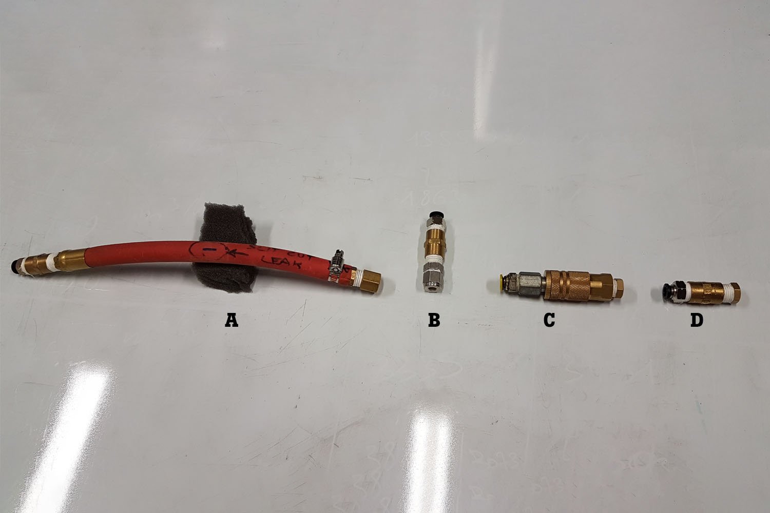
- Hose: Hose is a flexible tube that allows easy tubing. However, as opposed to the metal and brass pipe, it is a more sensitive material. Therefore, specific cut and holes are easily formed along with the hoses that connect an air compressor to pneumatic devices. A slit hose cut leak was used for capturing acoustic data of the hose leak for classification and flow rate prediction (Fig. 3 and Fig. 5a).
- Open-end: Open-end tube or an open orifice is the most common type of leak used in scientific studies (references). It occurs when a tubing/piping section of the compressed air system is left open. An open-end tube was used in classification and flow rate prediction experiments throughout the ii900’s development stage (Fig. 4 and Fig. 5b).
- Quick connect: Quick connect fittings, also known as quick-disconnect or quick release couplings, allow easy and fast connections. The quick-connect fittings rely on the tilts that slide in one direction and are resistant to pull in the opposite direction. Commonly, one or more of these inner tilts are damaged, and the compressed air leaks through the quick-connect fitting. The air scatters around the fitting, and the compressed air leak’s direction varies for each case of deformation. A deformed quick-connect fitting was used for acoustic measurements during the development of the Fluke ii900 and ii910 acoustic imager’s classification and flow rate prediction algorithms (Fig. 5c).
- Threaded coupling: It is common to use a threaded end cap for a compressed air system’s endpoint. The threaded end caps must be carefully placed and correctly adjusted concerning the number of threads that must slide into the end tube. Sometimes engineers may let these end-sections loose. Moreover, the threaded end caps can get deformed with multiple uses. In such cases, the compressed air leaks through the end cap, which is detrimental to the system’s efficiency. A loosely positioned threaded end cap was used as a leak source in the experiments (Fig. 5d).
Leak Rate Quantification index
The Fluke ii900 and ii910 acoustic imaging cameras provide an estimate of the flow rate at the leak position based on the acoustic data that is captured. The flow rate algorithms were designed based on the results of the laboratory measurements that were conducted in the semi-anechoic chamber. Due to each leak type’s different acoustic characteristics, there is one flow rate prediction algorithm for each leak type. Hence, flow rate estimation algorithms operate after the classification stage.
The predicted flow rate of a leak type is then converted into the leak rate quantification (LRQ) index. The LRQ takes a value between 0 and 10. The higher LRQ value indicates a larger flow rate at the leak position and can be considered a repairment suggestion.
Conclusions
The Fluke ii900 and ii910 acoustic imaging cameras provide an efficient frequency range and a user-friendly hand-held device solution that attempts to compensate for leak detection difficulties and quantification. The LRQ feature is critical for maintaining the compressed air system’s efficiency, and reporting functionalities improve the communication speed between the maintenance engineers.
References
[Eret] Eret, P., & Meskell, C. (2012). Microphone arrays as a leakage detection tool in industrial compressed air systems. Advances in Acoustics and Vibration, 2012.
[Harris] Harris, C. M. (1966). Absorption of sound in air versus humidity and temperature. The Journal of the Acoustical Society of America, 40(1), 148-159.
[Holstein] Holstein, P., Barth, M., & Probst, C. (2016). Acoustic methods for leak detection and tightness testing. In Proceedings, 19th World Conference on Non-Destructive Testing (pp. 13-17).
[Vladišauskas] Vladišauskas, A., & Jakevičius, L. (2004). Absorption of ultrasonic waves in air. Ultragarsas, 50(1), 46-49.
[Wolstencroft] Wolstencroft, H., & Neale, J. (2008). Characterisation of compressed air leaks using airborne ultrasound. Proceedings of Acoustics (AAS’08).