Fluke 17B MAX Digital Multimeter
Key features
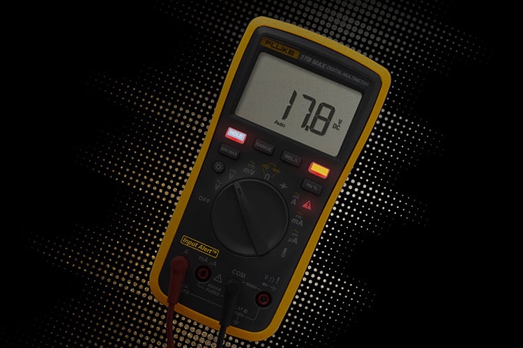
- Audible and visual alarm for incorrect connections
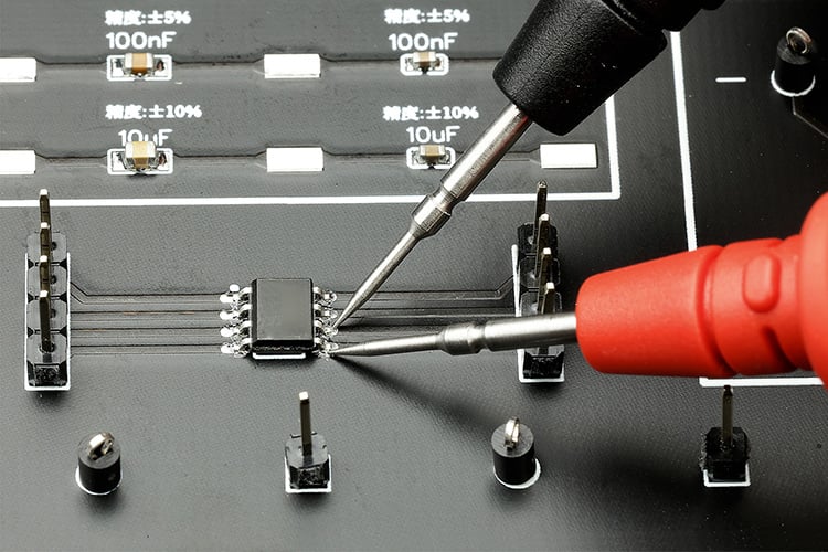
- Test leads with fines tips for circuit board testing
- Simple interface to wake meter from sleep mode by activating any buttons
- Voltage: 6000-count reading
- Capacitance range: 2000uF
- Safety rating: CATIII 600V
- Frequency and temperature measurement
Product overview: Fluke 17B MAX Digital Multimeter
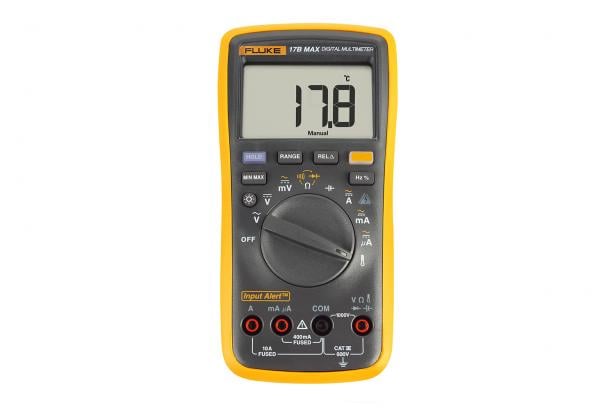
Fluke 17B MAX Inherits and continues the classic design of 17B+, with further improved functions: Input Alert Alarm, Simple interface to wake meter from sleep mode by activating any buttons, test leads with fine probes to help electricians and electronic R&D personnel make accurate measurements.

Audible and visual alarm for incorrect connections

Test leads with fines tips for circuit board testing
Specifications: Fluke 17B MAX Digital Multimeter
| Specifications | ||||
|---|---|---|---|---|
| Accuracy is specified for 1 year after calibration, at operating temperatures of 18 °C to 28 °C, relative humidity at 0 % to 75 % Accuracy specifications take the form of: ± ([% of Reading] + [Number of Least Significant Digits]). | ||||
| Function | Range | Resolution | Accuracy | |
| 15B MAX | 17B MAX | |||
| AC Volts (40 Hz to 500 Hz)1 | 6.000 V 60.00 V 600.0 V 1000 V | 0.001 V 0.01 V 0.1 V 1 V | 1.0 % + 3 | 1.0 % + 3 |
| AC Millivolts | 600.0 mV | 0.1 mV | 3.0 % + 3 | 3.0 % + 3 |
| DC Volts | 6.000 V 60.00 V 600.0 V 1000 V | 0.001 V 0.01 V 0.1 V 1 V | 0.5 % + 3 | 0.5 % + 3 |
| DC Millivolts | 600.0 mV | 0.1 mV | 1.0 % + 10 | 1.0 % + 10 |
| AC Current μA (40 Hz to 400 Hz)2 | 400.0 μA 4000 μA | 0.1 μA 1 μA | 1.5 % + 3 | 1.5 % + 3 |
| AC Current mA (40 Hz to 400 Hz)2 | 40.00 mA 400.0 mA | 0.01 mA 0.1 mA | 1.5 % + 3 | 1.5 % + 3 |
| AC Current A (40 Hz to 400 Hz)2 | 4.000 A 10.00 A | 0.001 A 0.01 A | 1.5 % + 3 | 1.5 % + 3 |
| DC Current μA2 | 400.0 μA 4000 μA | 0.1 μA 1 μA | 1.5 % + 3 | 1.5 % + 3 |
| DC Current mA2 | 40.00 mA 400.0 mA | 0.01 mA 0.1 mA | 1.5 % + 3 | 1.5 % + 3 |
| DC Current A2 | 4.000 A 10.00 A | 0.001 A 0.01 A | 1.5 % + 3 | 1.5 % + 3 |
| Diode Test3 | 2.000 V | 0.001 V | 10% | 10% |
| Temperature 4 | 50.0 °C to 400.0 °C 0 °C to 50.0 °C -55.0 °C to 0 °C | 0.1 °C | NA | 2 %+1 °C 2 °C 9 %+2 °C |
| Resistance (Ohms)5 | 400.0 Ω 4.000 kΩ 40.00 kΩ 400.0 kΩ 4.000 MΩ 40.00 MΩ | 0.1 Ω 0.001 kΩ 0.01 kΩ 0.1 kΩ 0.001 MΩ 0.01 MΩ | 0.5 % + 3 0.5 % + 2 0.5 % + 2 0.5 % + 2 0.5 % + 2 1.5 % + 3 | 0.5 % + 3 0.5 % + 2 0.5 % + 2 0.5 % + 2 0.5 % + 2 1.5 % + 3 |
| Capacitance6 | 40.00 nF 400.0 nF 4.000 μF 40.00 μF 400.0 μF 2000 μF | 0.01 nF 0.1 nF 0.001 μF 0.01 μF 0.1 μF 1 μF | 2 % + 5 2 % + 5 5 % + 5 5 % + 5 5 % + 5 5 % + 5 | 2 % + 5 2 % + 5 5 % + 5 5 % + 5 5 % + 5 5 % + 5 |
| Frequency1 (10 Hz to 100 kHz) | 50.00 Hz 500.0 Hz 5.000 kHz 50.00 kHz 100.0 kHz | 0.01 Hz 0.1 Hz 0.001 kHz 0.01 kHz 0.1 kHz | NA | 0.1 % + 3 |
| Duty Cycle1 | 1% to 99% | 0.10% | NA | 1 % typical7 |
| Continuity Threshold | — | — | 70Ω | 70Ω |
| Backlight | — | — | Yes | Yes |
| 1 All ac, Hz, and duty cycle are specified from 1 % to 100 % of range. Inputs below 1 % of range are not specified. 2 Typical burden voltage: DC/AC Current µA: 100 µV / µA; DC/AC Current mA: 2 mV/mA; DC/AC Current A: 0.03 V/A 3Typically, open circuit test voltage is 2.0 V and short circuit current is <0.6 mA 4Use Type K thermocouple 5 Typical open circuit test voltage is 0.54 V, maximum short circuit current is 1.8 mA 6Specifications do not include errors due to test lead capacitance and capacitance floor (may be up to 1.5 nF in the 40 nF range). 7 Typical means when the frequency is at 50 Hz or 60 Hz and the duty cycle is between 10 % and 90 %. | ||||
| Input Characteristics | ||||
|---|---|---|---|---|
| Function | Overload Protection | Input Impedance (Nominal) | Common Mode Rejection Ratio | Normal Mode Rejection Ratio |
| AC Volts | 1000 V 1 | >10 MΩ, <100 pF | >60 dB at 50 Hz or 60 Hz | — |
| AC Millivolts | 1000 V 1 | >1 MΩ, <100 pF | >80 dB at 50 Hz or 60 Hz | — |
| DC Volts | 1000 V 1 | >10 MΩ, <100 pF | >100 dB at 50 Hz or 60 Hz | >60 dB at 50 Hz or 60 Hz |
| DC Millivolts | 1000 V 1 | >1 MΩ, <100 pF | >80 dB at 50 Hz or 60 Hz | — |
| 1106 V Hz max | ||||
| General Specifications | |
| Maximum voltage between any Terminal and Earth Ground | 600 V |
| Maximum differential voltage between V and COM terminals | 1000V |
| Display (LCD) | 6000 counts, updates 3/sec |
| Battery Type | 2 AA, IEC LR6 |
| Battery life | 500 hours minimum |
| Temperature | Operating 0 °C to 40 °C; Storage -30 °C to 60 °C |
| Relative Humidity | Operating Humidity Non-condensing (<10 °C); ≤90 % RH at 10 °C to 30 °C; ≤75 % RH at 30 °C to 40 °C |
| Operating Humidity, 40 MΩ range | ≤80 % RH at 10 °C to 30 °C; ≤70 % RH at 30 °C to 40 °C |
| Altitude | Operating 2000 m; Storage 12000 m |
| Temperature Coefficient | 0.1 X (specified accuracy) /°C (<18 °C or >28 °C) |
| Fuse protection for current inputs | 440 mA, 1000 V, fast-blow, use only Fluke specified parts. 11 A, 1000 V, fast-blow, use only Fluke specified parts |
| Size (HxWxL) | 183 mm x 91 mm x 49.5 mm |
| Weight | 455 g |
| Ingress Protection | IP40 |
| Safety | IEC 61010-1, IEC61010-2-030: CAT III 600 V, Pollution Degree 2 |
| Electromagnetic Environment | IEC 61326-1: Portable |
| Electromagnetic Compatibility (EMC) | Only applicable in Korea |
Class A Equipment (Industrial Broadcasting & Communication Equipment)1
1Equipment meets requirements for industrial electromagnetic wave equipment and the seller or user should take notice of it. This equipment is intended for use in business environments and not to be used in homes.
Models: Fluke 17B MAX Digital Multimeter
Fluke 17B MAX-01 Digital Multimeter
Includes:
- TL75 Test Leads with 2 Protective Caps
- Type K Thermocouple
- 2 AA Batteries
- Safety information
Fluke 17B MAX-02 Digital Multimeter
Includes:
- TL31 Extra-Slim Test Leads with 2 Protective Caps
- Type K Thermocouple
- 2 AA Batteries
- Safety information
Fluke 17B MAX KIT Digital Multimeter
Includes:
- TL75 Test Leads with 2 Protective Caps
- TL31 Extra-Slim Test Leads with 2 Protective Caps
- Type K Thermocouple
- 2 AA Batteries
- Safety information


